Several properties are associated with a grid including the following:
Table 5 Grid Properties
- Dimension (required)
- 2D vs. 3D
- Grid type (required)
- Cartesian, curvilinear, extruded Cartesian, extruded curvilinear
- Extrusion type (optional)
- Type of extrusion used for K direction. Options include sigma stretch, Cartesian, curvilinear at corners, curvilinear at mid-sides. Must be defined for extruded grids.
- Global coordinate system (optional)
- Used to position the grid in 3D space.
- Origin (optional)
- The coordinates of the grid origin (I=0, J=0, K=0) in the global coordinate system
- Orientation (required)
- Right -hand or left hand rule
- Dip (optional)
- The angle of rotation about the global X axis (this is 0.0 for plan view 2D cases & 90 for vertically averaged 2D cases)
- Bearing (optional)
- The angle of rotation about the global Z axis
- Computational Origin (optional)
- The geometric corner of the grid that is the computational origin. By default this is the geometric origin (location 1).
- U Direction (optional - only applies to 3D case)
- The direction of the u axis which defines the position of the 3D grid triad on the geometric definition of the grid. This value defaults to either 1 or -1 depending on the computational origin.
- NumI (required)
- The number of cells in the I direction
- NumJ (required)
- The number of cells in the J direction
- NumK (required - 3D Grids only)
- The number of cells in the K direction (layers)
- Cartesian Grids
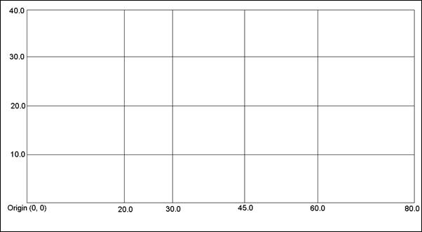
- For Cartesian grids the local coordinate location of each row, column, and layer (if 3D) boundary is specified. The first boundary in each direction is the local origin. Figure 7 shows a 2D Cartesian grid with the required grid cell boundary locations. The origin is always (0.0, 0.0) and therefore is not specified.
- Curvilinear Grids
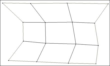
- Curvilinear grids must have all coordinates defined for each grid corner. For a 2D grid, there are (NumI + 1) * (NumJ + 1) corners. A 3D grid has (NumI + 1) * (NumJ + 1) * (NumK + 1) corners. Figure 8 shows a 2D curvilinear grid.
- Extruded Grids
- Some numerical models use grids that are 2D grids extruded in the K direction to form 3D grids. Both 2D curvilinear and 2D Cartesian grids can be extruded. The methods to extrude 2D grids include sigma-stretch, Cartesian, curvilinear at corners, and curvilinear at mid-sides. Sigma-stretch grids have top and bottom Kvalues (elevations) that may vary from column to column. Each layer of a sigma-stretch grid is a constant percentage of the K thickness. Cartesian extruded grids define constant K values for each layer in the grid (this is only used for 2D curvilinear grids because otherwise it would just be a 3D Cartesian grid). Curvilinear extrusion grids define the top and bottom K values for each layer and each corner or cell.
The CH3D hydrodynamic model supports 2D curvilinear grids extruded either by sigma-stretch or Cartesian. The groundwater model MODFLOW uses a 2D Cartesian grid extruded curvilinear at cell centers.
